bespoke design and manufacturing service for your specialist project. You imagine, we design.


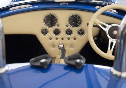
Our expertise in gauge design and investment in innovative technologies has placed us at the forefront as manufacturers of premium bespoke gauges

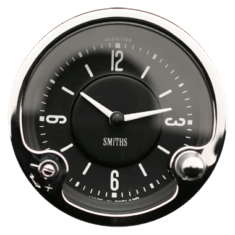
Our expertise in gauge design and investment in innovative technologies has placed us at the forefront as manufacturers of premium bespoke gauges
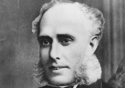
Trained craftsman and jeweller, Samuel Smith opened his first shop in Newington Causeway in London in 1851. A family business, it was founded as 'S. Smith and Son'.
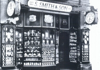
With growing demand, Samuel Smith (Junior) opened larger premises on The Strand, London and later, shops in Piccadilly and Trafalgar Square.
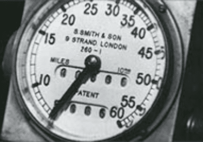
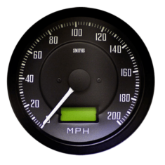
By the start of the 20th century and the age of the automobile, SMITHS had produced the first British speedometer and odometer ("mileometer").
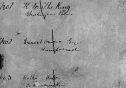
In 1904 the first Royal connection to SMITHS was established when King Edward VII asked Gordon Smith for a device to measure the travelling speed of his car. SMITHS historical records include a ledger of speedometer orders, the first of which has, as entry No. 1, 'H. M. The King, Buckingham Palace'.
In 1914 the public company S. Smith and Sons (Motor Accessories) Ltd was formed, manufacturing automotive speedometers, carburettors, and other motor accessories, with turnover exceeding £100,000.
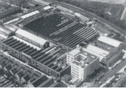
A new factory at Cricklewood, North-East London was built engaged in the manufacture of speedometers and employed 400 persons. The employees soon increased to 2,000 and they also made aircraft instruments and shell fuses for war time contracts.
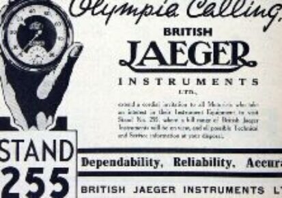
Smiths purchased 75 per cent of Ed. Jaeger (London) Ltd in 1927 which later became the British Jaeger Instrument Company.
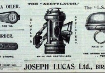
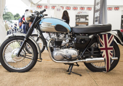
In 1930 SMITHS agreed a trading deal with Joseph Lucas Ltd. The mutual agreement meant the two would not compete in certain areas. Lucas continued to market a portion of the non-instrumentation SMITHS assets, and SMITHS became the dominant supplier of instruments to British motorcar and motorcycle firms.
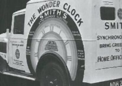
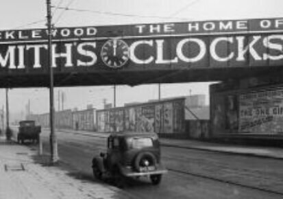
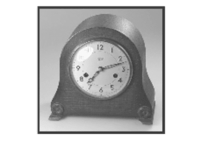
1931 S. Smith and Sons (Motor Accessories) Ltd, entered the domestic clock market and formed a new company, 'Smiths English Clocks', The Clock and Watch division of S. Smith and Sons (Motor Accessories) Ltd, continued to manufactured from the main factory at Cricklewood. Smiths became one of the first British manufacturers to produce synchronous electric clocks.
In 1932 Smiths purchased English Clock and Watch Manufacturer of Coventry and acquired the trade names Astral and Empire.
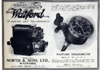
By 1933 Lucas had purchased North and Sons Ltd., a leading manufacturer of magneto, speedometers and other motor instruments. Lucas retained the magneto business whilst SMITHS concentrated on the speedometer and instrumentation business.
In 1934, Smiths bought the Enfield Clock Co; The shareholders were bought out, but SMITHS allowed the directors to remain and the company continued production from its premises at Pretoria Road, Edmonton. Due to low volumes, however SMITHS allowed Enfield to continue to trade independently.
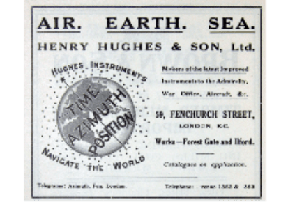
In 1935 SMITHS Acquired 'Henry Hughes and Son'; marine gauge manufacturers which specialised in navigation instruments and appliances for the British Navy.
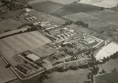
In 1939 Ralph Gordon-Smith, arranged the purchase of new 300 acre site, Kayte Farm at Bishop's Cleeve, Cheltenham to protect the business from potential bombing in the London area. On 1st June S. Smith and Sons (Cheltenham) Ltd was formed as a subsidiary of the main business.

By August 1940 the main instrument repair department at Cricklewood was destroyed by bombing. As a consequence of the war, demand for motor, aircraft and marine instruments for the Services surged and the production of industrial instruments, hitherto imported, was begun. Fuses for shells were also manufactured.
By 1944 a major regrouping of the whole SMITHS organisation was carried out. The name of the principal company was changed to S. Smith and Sons (England) Ltd with four divisions: 'Smiths Motor Accessories'; 'Smiths Industrial Instruments'; 'Smiths Aircraft Instruments' and 'Smiths English Clocks'.
By 1947 The company had grown exponentially with 17,000 employees. By the start of the 60's separate 'Smiths Aviation' and 'Smiths Marine divisions' were formed as well as an industrial instrumentation division. By 1964 the SMITHS group employed over 25,000 in 27 factories in the UK.
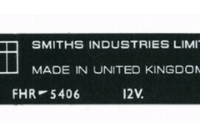
By 1965 the Smiths business had become increasingly diluted. As such the name 'Smiths Industries' was adopted to reflect it's wider operations. The clock and watch business had now declined and Smiths ceased to be the direct supplier of motor equipment to European car manufacturers.
In 1968 SMITHS received the Queen's Award to Industry for its contribution to UK Technological Innovation.
The production of the SMITHS tachograph increased from 400 units to 4000 units per month, owing largely to new legislation, which meant by 1978 all commercial vehicles must be fitted with tachographs. By now volume orders were being received from British Leyland, Ford and more.
By 1979 due to a decline in demand, a proposal was made to restructure and reorganise the motor vehicle component businesses and by 1981, a further reorganisation of the motor marine business followed.
The automotive instrumentation business was sold to Lucas. Lucas introduced wiring harness manufacture to the Ystradgynlais factory and become the largest employer in the area, employing a local workforce of over 2000.
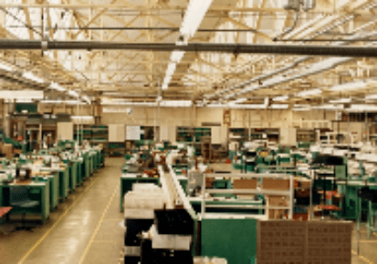
In 1989 Lucas transferred its instrumentation business to the Caerbont facility in neighbouring Abercrave but retained manufacture of its wiring and harness business at Ystradgynlais.
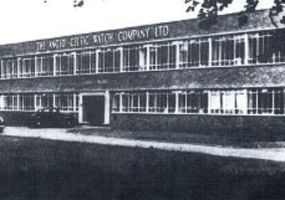
LUCAS decided to withdraw from the instrumentation market to concentrate solely on its wiring and harness manufacture. The business was sold to German company Mannesmann VDO AG and was managed by its parent UK company VDO Birmingham.
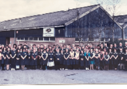
In 1993 the management purchased the business from Mannesmann VDO AG and renamed it Caerbont Automotive Instruments Ltd. The business continued to supply to mass markets although by now the direction was evolving more into bespoke and heritage markets.
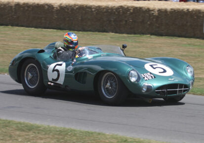
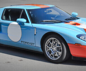
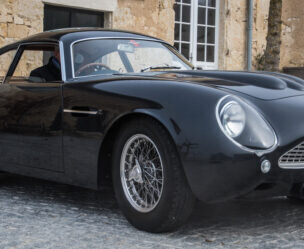
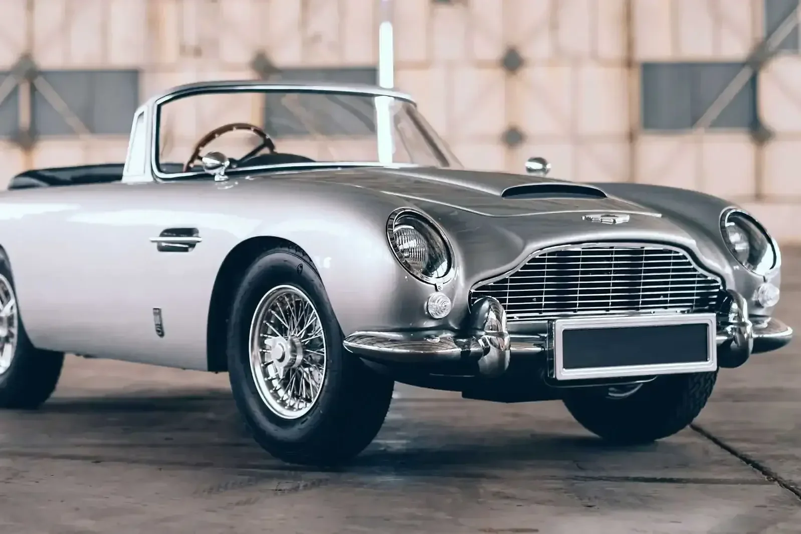
By 2011 ownership transferred to the present MD Gavin Roberts. The business retained its name and continued to supply SMITHS gauges. Today, the business has evolved into new markets such as bespoke marine and automotive instrumentation but also continues to supply heritage gauges to high profile prestige marques like Jaguar and Aston Martin.